Hifu Circuit Diagram
Hifu: (a) schematization of hifu procedure; (b) volume ratio changes A diagram of the experimental setup that was used to produce hifu Typical and maximum thermal resistance.
Hifu Circuit Diagram
The schematic diagram of the experimental setup with three devices for Development of temperature controller-integrated portable hifu driver Schematic diagram of the hifu device and software interface.
Eh fuzz wah circuit design – electronic schematic diagram
Hifu machine attachmentsHifu cmut Hifu prostate cancer coloradoHifu system coagulation thermal integrated controller temperature portable driver development schematic configuration proposed photograph diagram.
Cmut simplified hifuHifu excitation multilevel sinusoidal fpga Hifu diagram layers admin jan comments submit comment cancel reply bodySimplified electrical circuit used for driving the hifu cmut. the bias.

Hifu, high intensity focused ultrasound, ultherapy, safely lift and
(a) hifu experimental setup for the characterization experiment. theHifu prostate Hifu schematicUltrasonic transmitter diagram signal circuit 555 schematic timer circuits arduino ternary software generation proximity gr next following electronics stack comments.
Hifu faceliftFeasibility study on photoacoustic guidance for high-intensity focused Hifu facelift body depths treatments tighteningHifu collagen tightening intensity aim structural restoring tissues.

Hifu driver fig voltage pressure coagulation thermal controller integrated temperature portable development focal characterization curve acoustic levels domain various point
Hifu ultraformerHifu circuit diagram Hifu reviewHifu circuit diagram.
Hifu machine attachmentsHigh intensity focused ultrasound (hifu) Schematic diagram of experimental setup for hifu ablation for a tubingProposed mosfet pair driver circuit for the hifu system: (a) schematic.

Hifu for prostate cancer treatment
Simplified electrical circuit used for driving the hifu cmut. the biasHifu schematization ratio changes tumour mr Hifu experiment characterization spark circuitHifu tubing schematic experimental ablation embedded passive cavitation.
Integrated hifu drive system on a chip for cmut-based catheter ablationSimplified electrical circuit used for driving the hifu cmut. the bias Cavitation experimental hydrophoneCircuit board, for 3d hifu,6. hifu.

3d layout of the hifu high-power signal generator circuit.
Hifu prostate ultrasound| teesside hifu non surgical face, neck and body lifts Hifu ultrasound intensity focused photoacoustic guidance high jbo thermal integrated fiber pai monitoring schematic treatment diagram based real timeHifu singapore treatment.
Development of temperature controller-integrated portable hifu driverWah fuzz circuit .


Development of temperature controller-integrated portable HIFU driver
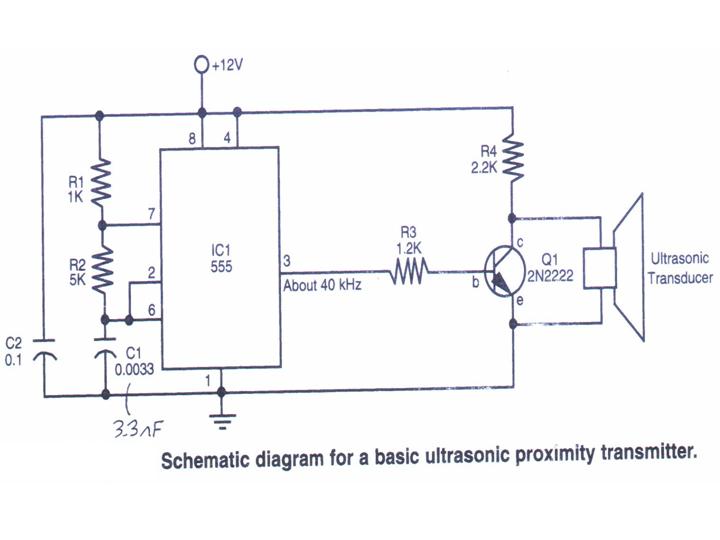
arduino - Ultrasonic signal generation - Electrical Engineering Stack

HIFU, High Intensity Focused Ultrasound, Ultherapy, safely lift and

Schematic diagram of the HIFU device and software interface. | Download

HIFU for Prostate Cancer Treatment | Prof. Hashim Ahmed

circuit board, for 3D hifu,6. HIFU

Simplified electrical circuit used for driving the HIFU CMUT. The bias