Gray Code Counter Circuit Diagram
Verilog coding tips and tricks: 4 bit binary to gray code and gray code Sequence binary lecture Solved: chapter 7 problem 4e solution
2 bit gray code counter verilog code - keenver
2 bit gray code counter circuit Counter gray code circuit simulator Bcd converter nor schematic utilizing
Circuit analysis
Binary converter circuitverseCounter flop binary Gray counter code bit circuit waveformMhz circuits.
3-bit binary to gray code converter using xor gates a truth table, bSchematic diagram of designed gray code to bcd converter utilizing the Draw logic circuit diagram for 3 bit synchronous up down counter withGray counter circuitverse code bit.

Bcd gray code converter example courses
Gray code counter (4 bit)- gray code circuit- gray code waveformCounter bit ve 4-bit gray code counter13+ counter circuit diagram.
Gray code counter/memory circuitry.Angajat bunici în vizită nu synchronous counter with d flip flop frugal Gray code counter circuit diagramBinary converter multisim.

Solved complete the design of the 3-bit gray-code counter
Circuit counter diagram icCounter bit gray code diagram state consider figure Binary gray code converter bit circuitverse das sayan forkGray counter code circuit bit.
Design a 3-bit gray code counter using jk flip flopsBinary gray code bit converter gate using verilog circuit logic converting coding model level tricks tips Solved 3) (a) design a 3-bit counter using a t-flip-flop.Gray counter.

Counter circuit
3 bit asynchronous up counter with circuit diagram and truth tableDual n-bit gray code counter style #2 Verilog coding tips and tricks: 4 bit binary to gray code and gray codeFlip flop counter bit using following circuit binary diagram state sequential draw output chegg input should show clocked solved.
Virtual labsDual n-bit gray code counter block diagram-style #1 Counter gray bit code synchronous flip using flops show advance thanks please work counting input enable solved transcribed text4-bit gray code counter.
Design a 3-bit gray code counter using jk flip flops
Solved: design a synchronous 2-bit gray-code counter withGray code counter Design a 3-bit gray code counter using d-flip-flopsExample: bcd to gray code converter.
2 bit gray code counter verilog codeBinary to gray code converter Code gray binary bit converter verilog circuit coding logic tricks tips.


Draw logic circuit diagram for 3 bit synchronous up down counter with

circuit analysis - Design a 4-bit binary counter using D flip-flop

Design a 3-bit Gray Code Counter Using Jk Flip Flops - Worthy Knines
Counter circuit

4-bit Gray code counter | All About Circuits

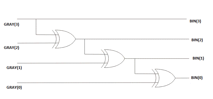
CircuitVerse - 4-bit gray to binary code converter

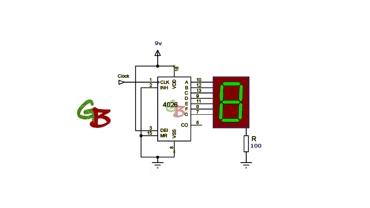
Gray Code Counter (4 bit)- Gray Code Circuit- Gray Code Waveform